
The new revolutionary technology accessible to almost everyone is arguably 3D printing technology. All that is needed is a couple of files describing the structure and dimensions of the required object with precision, provide the input to a 3D printer, and there you have it, a real-life model of that very object. The integral software part here is the modeling program that is to be used for designing the model.
Not just that aspect, but 3D printing is also a beneficial factor for people contributing to and interested in open-source hardware projects. Casings can be made, or rather printed, pretty easily. Today, we’re going to talk about one such modeling program that is key to all this power, BRL-CAD.
Features
BRL-CAD on the official websites boasts being used by the U.S. Military for more than 20 years. It has been their major testing and modeling platform. This must mean that it has some special features that are rather desirable.
Solid Modelling
Solid modeling provides a physically accurate representation of the models created. This results in ease for creating real-life and practical projects to be used. Especially things that have to interact with the environment a lot, like automobiles.
Raytracing
Raytracing is an important factor, making geometric analysis easier for the models being created. These can include calculating the moment of inertia, the position of the center of mass, pressure at a spot, etc. It also makes rendering images easier for reviewing process.
Scripting Interface
BRL-CAD can run series of commands directly input by the user using the standard input and has better efficiency as it can pack multiple commands together rather than the user having to insert each command separately, one after another.
Procedural Geometry
BRL-CAD can create models using the procedural geometry interface, which creates models based on algorithms and equations rather than manual construction.
Performance
BRL-CAD has a very efficient design, considering the structure of on-disk and in-memory storage. BRL-CAD can run performance-intensive processes, even on low powered systems, due to its better design. Other than that, BRL-CAD also has a modular design, which means tweaking the program much easier.
Download and Install
There are different installation instructions available, but the latest release has very complicated ones. We will show the simplest ones here, so just follow along.
First off, the dependencies. BRL-CAD’s installation will require two programs:
For Ubuntu/Debian based systems:
sudo apt install cmake subversion
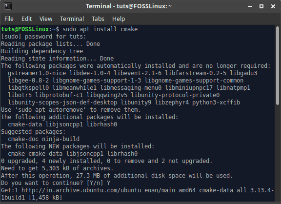
Installing prerequisites
For Fedora-based systems:
sudo dnf install cmake subversion
You can enter your own system equivalent, as these programs are widespread.
Now for downloading the files of BRL-CAD:
svn checkout https://svn.code.sf.net/p/brlcad/code/brlcad/trunk brlcad

SVN checkout
There will be a directory named brlcad as a result of this command. Now execute the following:
mkdir brlcad/build
cd brlcad/build
cmake .. -DBRLCAD_BUNDLED_LIBS=ON -DCMAKE_BUILD_TYPE=Release
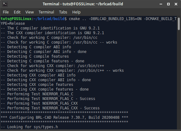
Cmake result
Now for compiling the program:
make

Make command result
And finally, installation:
make install
BRL-CAD WalkThrough
Now that you have BRL-CAD installed on your Linux system, you have no excuse but to re-pursue your architectural hobby and design that house you imagined in your head. Alternatively, you are now able to design awesome robotic parts for your engineering projects, or you can just copy-and-paste the world designs that you fancy and think should reside in your modeling portfolio. Before this tutorial article immerses you into the intriguing maze of 3D CAD (Computer-Aided Design) modeling, we should make acquaintance with what modeling really is so that you have a third-eye view of the way you perceive shapes.
BRL-CAD Perspective on Modeling
In the world of Computer-Aided Design or CAD, a model is anything visual, analytical, and printable. It is because modeling is a study mirrored image of actual objects in the real world. When we fuse CAD with modeling, we have CAD modeling, which facilitates the actual representation of the objects perceived with our eyes or imagination and creates a realistic representation of these objects with specific dimensions. The outcome of a modeled 3D object will portray the same physical characteristics applicable to an object existing in the real world.
Since we are now well acquainted with the power of this 3D solid modeling system, a brief tutorial on how to use it should be enough tribute to the unsettled beginners or enthusiasts that are looking for a solid foundation to mark their territory in the BRL-CAD world. Once you get a grip on how to maneuver around BRL-CAD, you will understand why it dynamically fits in industrial, education, and military applications.
The next part of the article will familiarize you with BRL-CAD’s User Interfaces, Menu Items, Databases, and other basic functionalities. We should also be able to demonstrate a basic modeling tutorial.
Introducing MGED
MGED is short for Multi-Device Geometry Editor. There are many other applications to explore under BRL-CAD software, but after accomplishing some modeling objectives, this article is considering going with MGED.
The first step is to power up your Linux terminal either from the OS application menu or by using Ctrl + Alt + T, which is proven to work for Ubuntu. Once your terminal is live, execute the following command:
$ mged
You may get an error that your Linux system cannot find this mged command or not recognized as a system command. The issue here is usually with the path configuration directly linked to where you installed your BRL-CAD software. If you can trace and specify this new path, then you should be able to use the mged command successfully.
The default installation directory for BRL-CAD is /usr/brlcad. If you are getting an unwanted error while using mged command from your terminal, your Linux system might be having trouble trying to trace this installation directory. Your Linux system execution path needs to recognize the directory path /usr/brlcad/bin to fix the issue. Running the following commands will make the needed changes on your ~./profile or ~./bash_profile. It depends on the terminal type or shell that you are using.
$ PATH=/usr/brlcad/bin$PATH
$ export PATH
Ensure you are on the right shell before adding the path statement to avoid unwanted system errors. You can check the shell you are currently using through this command.
$ echo $SHELL
Now, if you were having issues using mged, re-typing the command again should not prompt any errors.
$ mged
When this command executes successfully, expect a pop up of two MGED windows. The pop-up with the clear, bright screen or one with the terminal instance mged> is the MGED Command Window, and as its name suggests, you will be using it to execute your many BRL-CAD-related commands. The other pop up is the MGED Graphics Window. The BRL-CAD community popularly refers to it as the Geometry Window. It is a graphical reflection of the commands implemented under the MGED Command Window. You can think of these two windows as having a backend to frontend relationship like the case with desktop and web apps where one side holds the logic code and the other side displays the achievement of the logic code.
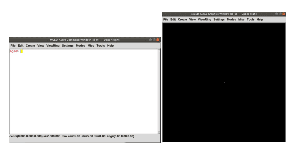
MGED Command Window and Graphics Window
It is possible to achieve CAD modeling through the MGED Graphics Window, but considering using the MGED Command Window will give us some modular flexibility on how we achieve our modeling objectives.
Dealing with a Database
The first step to launching and pursuing your CAD modeling hobby or career via BRL-CAD is to create a database via the MGED interface or window. Use your computer mouse to navigate to the MGED Command Window and input the following command string.
mged> opendb demo.g
The above command tells MGED to create a database called demo. As you have realized, created database files under BRL-CAD will always take the .g file extension. Once you hit enter on your keyboard, MGED will check if the database name you have given does exist, and if it doesn’t, you will be prompted to confirm its creation. If it exists, the already existing database will be the one that opens up through this graphics window.
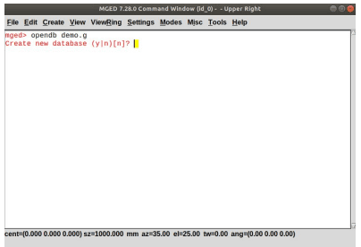
Creating a BRL-CAD Database via MGED
BRL-CAD Modeling Approaches
There are two main approaches to achieving modeling through BRL-CAD software. The first approach is by employing primitive shapes, and the second approach is by using basic Boolean operations on these same shapes. To understand the first approach, we need to define a primitive shape. If you take a 3D object and change its parameters like height, width, base, or radius without altering the shape’s type, then you have a primitive shape. One such basic 3D object that qualifies as a primitive shape is a sphere, and BRL-CAD hosts a dozen more like it in its database.
The second modeling approach of using basic Boolean operations exists because not all shape models you will be dealing with will have the primitive model trait. Basic Boolean operations like intersection, subtraction, and union will be required to achieve the desired model output. A practical modeling example is taking a larger closed cylinder and then subtracting a smaller cylinder portion from it to create a hollow cylinder successfully.
These are the modeling approaches you need to master under BRL-CAD. You will have to master a few commands to fuel your modeling pursuits, and after that, anything and everything that concerns the modeling world will bend its knee to your will.
Our Tutorial Modeling Target and Objective
To have a solid foundation in modeling under BRL-CAD, we will reference BRL-CAD’s documentation tutorial on modeling a complete chess set. We will try and touch on the fundamental aspects of modeling that will help you grow by trying to be as blunt as possible in our explanations. Since it is a 3D modeling walk-through, Arthur Shlain’s2D design will be our reference base.
The members of a chess set consist of a King, Queen, Knight, Rook, Pawn, and Bishop.
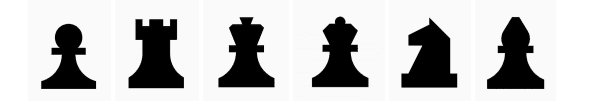
Members of a Chess Set
For this tutorial article to be interesting, we will accomplish only one modeling adventure for you in regards to the listed members of the Chess set. The rest you can comfortably accomplish for yourself afterward as a home assignment. Alternatively, you can take the skills you will learn from creating this single chess piece and explore other modeling challenges that will make you a better BRL-CAD modeler.
We cannot toss a coin on which members of the chess set team to model due to their number, but we can roll a dice since we are dealing with six chess pieces. The dice roll on my side decided to go with the pawn piece. Well, since you are still a soldier in this BRL-CAD tutorial who is yet to acquire the deserved CAD modeling skills, it makes perfect sense. Without the Pawn on a chessboard, all the other members of the chess set are vulnerable and exposed to complete ambush.
Modeling a Pawn Chess Piece

The Pawn Chess Piece
The first obvious step is creating a database for our Pawn piece with the .g extension as specified earlier. Use the MGED Command Window to accomplish this task.
mged> opendb pawn.g
Press enter on your keyboard.
Create a Cylinder that Defines the Base of Our Pawn Model
With the Command Window active, input and execute the following command strings:
mged> in base.rcc rcc
This command string is useful in creating a circular cylinder. The in part of this command inserts a primitive shape. The second part, base.rcc, is the definitive name to this primitive shape, and the third part of the command, rcc, specifies that the shape we are creating is a Right Circular Cylinder.
MGED will then prompt you for x, y, and z vertex values. These values define the bottom-center of your defined primitive shape. Input the following values and press enter.
mged> 0 0 0
Spacing is important when dealing with such values. So adhere to the spacing convention.
The next prompt from MGED will request the height vector values (x, y, z) for the creating cylinder. Go with the following input and press enter.
mged> 0 0 0.6
Finally, the last input prompt value requested by MGED will define the radius of the base of our to-be-created cylinder shape.
mged> 2.25
Your final MGED command window should resemble the following screenshot.
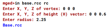
MGED Command Window with Cylinder Base Values
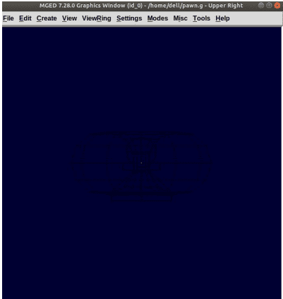
When you navigate to the Graphics Window, the magic that happened while you were on the Command Window should be similar to the following screenshot.
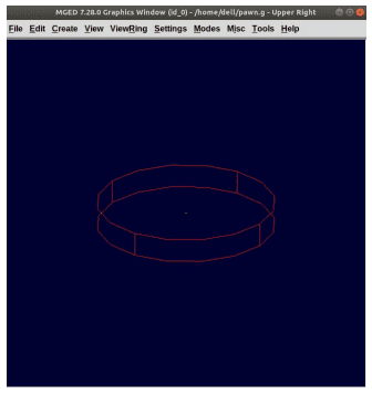
Cylinder Base Representation on MGED Graphics Window
There is an easier way to accomplish all these steps above, creating the cylinder base. We can achieve all the steps above in a single command string. Consider the following use of in command to accommodate all the needed parameters for creating a cylinder base shape.
mged> in base.rcc rcc 0 0 0 0 0 0.6 2.25
When you press enter, the command will achieve the final objective of the many steps listed above, creating a representation of a defined cylinder shape. We can summarize the implications of the above command parameters as:
in: performs the insertion of a primitive shape
base.rcc: the name of the defined primitive shape
rcc: the shape of the defined primitive object, in this case, a right circular cylinder
0: vertex X value
0: vertex Y value
0: vertex Z value
0: height vector X value
0: height vector Y value
0.6: height vector Z value
2.25: the base radius of the defined primitive shape
Since this command string approach seems more organized and direct, you should adopt it in all your modeling projects. Now that we have the base of our Pawn chess piece, we want to model it going upwards. The next portion to model is the curvy region above the base.
Create the Curvy Part of Our Pawn Model
Accomplishing this objective can be a bit of a challenge, but nothing is impossible in the eye of FossLinux. There are two steps that we need to conquer. First, we will define a trc (Truncated Right Cone). Secondly, we will subtract a Torus from the defined trc’s outer portion (tor). You can think of tor as a 3D circular revolution model since we do not want to get lost in the intense world of geometry.
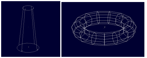
Truncated Right Cone and Torus representations
We will start with trc.
mged> in body.trc trc
Press enter. We want this trc we are defining to begin from rcc model’s top part. To be specific, let us go with the 0.6 height value. As usual, MGED should have prompted you for the vertex values X, Y, Z for the bottom-center portion of the trc model. Enter the following values and press enter.
mged> 0 0 0.6
The next MGED prompt will request the height vector’s X, Y, Z values. Also, enter the following values and press enter.
mged> 0 0 1.7
MGED will then ask for a base radius value. Ensure this radius value is the same as the one for the base.rcc. Your rhyming input value here should be:
mged> 2.25
The last MGED value request will be regarding the top radius; we decided to follow the following value input. Key it in and press enter.
mged> 0.5
Your graphics window for our Truncated Right Cone should resemble the following screenshot:
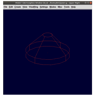
Truncated Right Cone Graphics Window
We will pursue the in command short-hand method to accomplish the objective of creating the curvy part of the Pawn model. The following command string should suffice. Copy it on your Command Window and press enter.
mged> in curve.tor tor 0 0 2.8 0 0 1 2.85 2.35
The vertex values X, Y, Z, are represented by 0 0 2.8. We arrived at the 2.8 value by adding body.trc’s vertex value Z, height, and top radius respectively (0.6 + 1.7 + 0.5). The X, Y, Z values 0 0 1 apply to the normal vector that will create the perpendicular tube inline with the z-axis. Radius 1 is 2.85, and radius 2 is 2.35. Radius 1 is defined from the tube’s center to the vertex, and radius 2 is the generalized tube radius.
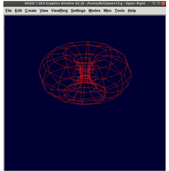
A more visual representation and explanation of radius 1 and radius 2 are evident in the following screenshot.

Torus Radius 1 and Torus Radius 2
Creating the Neck Cylinder for Our Pawn Model
The MGED terminal command to use here is the following.
mged> in neck.rcc rcc 0 0 2.3 0 0 0.5 1.4
Press enter. First, we are creating a cylinder with vertex 0 0 2.3. The vertex value 2.3 is the sum of the body.trc’s height and vertex. It is the only way to ensure that the Pawn model’s neck is positioned on top of the Pawn model’s base. We also specified the defined cylinder’s height vector with the values 0 0 0.5. The last value, 1.4, represents the defined cylinder’s radius.
Creating a Head Sphere For Our Pawn Model
The MGED terminal command to use is the following:
mged> in head.sph sph 0 0 3.6 1.1
Press enter. The .sph extension in this command string implies defining a sphere. The sphere vertex values are 0 0 3.6, and the Sphere radius value is 1.1. The sphere vertex value, 3.6, is the sum of neck.rcc’s half-height value (0.25), vertex value (2.3), and this sphere’s radius (1.1). To effectively visualize the current status of the Pawn model we have created so far, use your computer’s right and left mouse buttons to zoom in and out, respectively.
Pawn Model Status After Implementing its Neck and Head
Navigate to MGED Graphics Window’s menu bar, click on the View menu item, and then select Front. You should be able to create a front view display of your current Pawn model status.
Front View of Our Current Pawn Model
Creating a Region for Our Pawn Model
When we create a region, we are implying that we want to bring our model shape into existence. Every model shape you create will have to go through this step, where our model shape will be given mass and the ability to occupy space. Executing this region’s construction will demand the application of Union, Subtraction, and Intersection Boolean operations. Execute the following MGED terminal command.
mged> r pawn.r u base.rcc u body.trc – curve.tor u neck.rcc u head.sph
The r part of the command string creates a region and gives it the name pawn.r. The u part of the command string includes the model shape volume of a listed model shape following it, and the – part of the command excludes the model shape volume of the listed model shape succeeding it on the command string.
We can conclusively state that the above command includes all the model volumes of the model shapes we created earlier except the one for curve.tor, which is excluded from body.trc.
Implementing Material Properties on Our Created Pawn Model Region
The MGED command used here is straight forward and looks like the following.
mged> mater pawn.r
Press enter. MGED command prompt response from executing the above command is similar to the screenshot below:
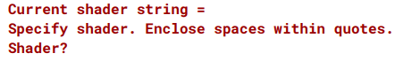
MGED Command Prompt Response When Defining a Model Region’s Material Properties
MGED is simply asking you about the material type that should define your Pawn model region. Let’s say we want the pawn model region to be plastic; we will give MGED the following input as our response:
mged> plastic
The next MGED prompt will request an input RGB color code that should define our Pawn model’s appearance. You can pick any color, but since we decided to go with black, the needed input is:
mged> 0 0 0
The last MGED prompt will ask whether your Pawn model should have material inheritance properties. Typing 0 is No, and typing 1 is Yes. Go with No.
mged> 0
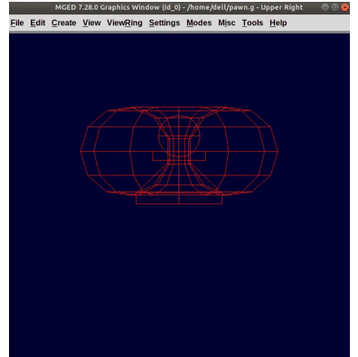
Implementing the New Region by Clearing the Current Graphic Window
We can see our Pawn region fused with some other shapes we do not want from the Graphics Window. They are the old designs that helped us to reach this step of the tutorial, but it is time to part ways with them. Execute the following command and press enter:
mged> B pawn.r
Excluding Old Model Designs from Our New Region
If you want to be sure that the above command is executed successfully, you will notice the curve.tor appears to be dotted. It is an indication that it is excluded from our new region. The B command is a blast command that draws the traced region (pawn.r) after clearing off the graphics window. The Blast command is a fusion of the draw and Z commands. The Z command undoes a region, and the draw command traces the remaining region back to life.
Raytracing Our Pawn Model
Here, you will navigate to the Graphics Window menu bar, trace the File menu item and click on the Raytrace sub-menu item. A Raytrace Control Panel dialogue box will pop up. Use this control panel to set a background color from the provided Background Color menu. Go with a white background because our Pawn model is defined as black. It will make it clearly distinguishable. The model shapes outline or wireframes can be eliminated from the Raytrace Panel’s Framebuffer menu by selecting the Overlay submenu item under it. The following screenshot depicts the finished product of your aspiring Pawn chess piece. Long live the King served by Pawns!
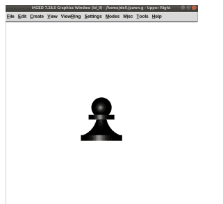
Final Pawn Chess Piece Model
Final Note
If you managed to successfully install BRL-CAD software on your Linux system and also managed to model the Chess Pawn piece, then you deserve a warm pat on your back. By creating this Pawn chess piece, you have covered CAD modeling fundamentals with BRL-CAD. You now know how to create a base, body, neck, and head of a model piece, something not easily achievable. Creating something like an architectural 3D house model should not be an issue. You can even go further in robotics and create robotic arms or full model prototypes, which can be career-defining for you both in the robotics field and gaming arena. Your imagination is the limit of what you can model. The chess move is yours; protect your King or be the King! Either way, you still win!